02-3439-2208 A/S 신청 및 상담
02-3439-2203/2205/2206gwinstek@gwinstek.co.kr 제품기술문의
 > TEXIO 제품 > DC 전자부하
 LW 시리즈
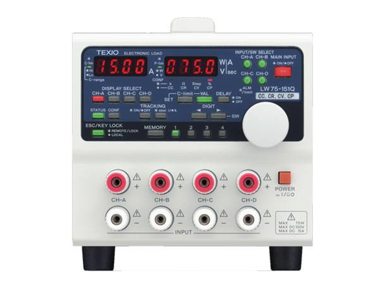
- 프로그래머블 벤치탑 DC 전자부하, LW
- 입력 채널 : 1CH/2CH/4CH
- 입력 전압 : 1V~150V
- 입력 전류 : 0~15/30/60A
- 입력 전력 : 75W/150W/300W
- 인터페이스 : USB/GPIB(옵션)
|
주요 특징 • Multi-channel & individual control - Each channel is isolated and can be controlled individually. • Low cost High performance - The CC and CR modes are standard. Addition to standard, CV and CP modes are lined up. Various models are available based on usage scenes. • 4 points presetting - 4 sets of frequently used value can be preset. • Key lock - Key lock function provides to hold all setting values. • Various remote controls (user option) - It is possible to add the interface function of GP-IB or USB after purchasing as user option. • Front input terminal (1A/3A/7A models) - The terminal is provided by factory option. (Maximum input current is 30A.) • Maximum 12 channel in full rack size | |||||||||||||||||||||||||||||||||||||||||||||||||||||||||||||||||||||||||||||||||||||||||||||||||||
|
Lineup
| |||||||||||||||||||||||||||||||||||||||||||||||||||||||||||||||||||||||||||||||||||||||||||||||||||
|
Specifications | ||
|
Maximum Input Rating | ||
|
Input voltage |
LW75-151Q |
H current range: 75 W, L current range: 12.5 W |
|
LW151-151D |
H current range: 150 W, L current range: 25 W | |
|
LW301-151S |
H current range: 300 W, L current range: 50 W | |
|
Input current |
LW75-151Q |
H current range: 15 A, L current range: 2.5 A |
|
LW151-151D |
H current range: 30 A, L current range: 5 A | |
|
LW301-151S |
H current range: 60 A, L current range: 10 A | |
|
LW301-151S |
H current range: 30 A, L current range: 10 A | |
|
Application voltage |
All models |
150 V |
|
Inputterminals |
LW75-151Q |
4 (Std.: rear, factoryoption: front) |
|
LW75-151D |
2 (Std.: rear, factoryoption: front) | |
|
LW301-151S |
1 (Std.: rear, factoryoption: front) | |
|
Constant-Current Mode | ||
|
Input vol. range |
All models |
Rear: 1 to 150 V |
|
Setting range |
LW75-151Q |
H current range: 0.000 to 15.750 A (0 to 105% FS) |
|
LW151-151D |
H current range: 0.000 to 31.500 A (0 to 105% FS) | |
|
LW301-151S |
H current range: 0.000 to 63.000 A (0 to 105% FS) | |
|
LW301-151S |
H current range: 0.000 to 31.500 A (0 to 105% FS) | |
|
Theoreticalresolution |
LW75-151Q |
H current range: 1 mA |
|
LW151-151D |
H current range: 2 mA | |
|
LW301-151S |
H current range: 5 mA | |
|
Setting accuracy |
All models |
±(0.5% SET + 0.3% FS)at 23 ±5℃ 1% FS current or more |
|
Ripple noise |
LW75-151Q |
H current range: 5 mA |
|
LW151-151D |
H current range: 10 mA | |
|
LW301-151S |
H current range: 20 mA | |
|
Temperaturecoefficient |
All models |
100ppm/℃: time of rated current |
|
・The constant-current circuit of the LW series has an internalreference power source for each preset. Thus, whenthe same current is set for all presets, the control current may differ withthe presets. | ||
|
Constant-Resistance Mode | ||
|
Input vol. range |
All models |
Rear: 0 to 150 V, front: 0 to 150 V |
|
Setting rangeResistances shown on right correspond to STEP values of 3 to 30000. |
LW75-151Q |
H current range: 1 k to 0.1 Ω L current range: 6 k to 0.6 Ω |
|
LW151-151D |
H current range: 500 to 0.05 Ω L current range: 3 k to 0.3 Ω | |
|
LW301-151S |
H current range: 250 to 0.025 Ω L current range: 1.5 k to 0.15Ω | |
|
Theoreticalresolution |
LW75-151Q |
H current range: 333.μS (= 1/3 k Ω) |
|
LW151-151D |
H current range: 66.6 μS (= 1/1.5 k Ω) | |
|
LW301-151S |
H current range: 1.33 mS (= 1/750 Ω) | |
|
Setting accuracy |
All models |
±(2% Vin/Rset + 1.5% FS current) |
|
Ripple noise |
LW75-151Q |
H current range: 5 mA |
|
LW151-151D |
H current range: 10 mA | |
|
LW301-151S |
H current range: 20 mA | |
|
Temperature coefficient |
All models |
1000ppm/℃: time of rated electric power and time of rated |
|
・The resistance shown above arecalculated using thefollowing expression: Resistance=1/(theoreticalresolution x STEP) ・The constant-resistancecircuit of the LW series has an internal reference power source for each preset. Thus, when the same resistance is set forall presets, the control resistance may differ with thepresets. ・The constant-resistance circuit of the LW series switches threecircuits to execute resistance control accordingto the set steps. Thus, the setresistance may change greatly in the setting accuracy range whenthe circuit is switched (at two points between the set steps 300 and 301 andsteps 3000 and 3001). | ||
|
Constant-Voltage Mode | ||
|
Setting range |
All models |
0.00 to 157.50 V (0 to105% FS) |
|
Min. operating current |
All models |
1% FS current |
|
Theoretical resolution |
All models |
10 mV |
|
Setting accuracy |
All models |
±(0.5% SET + 0.3% FS)at 23 ±5℃ |
|
CV temperature coefficient |
All models |
150 ppm/℃: time of rated voltage |
|
・The constant-voltage circuit of the LW series has an internalreference power source for each preset. Thus, whenthe same voltage is set for all presets, the control voltage may differ withthe presets. | ||
|
Constant-Power Mode | ||
|
Input vol. range |
All models |
H voltage range: 5 to 150 V L voltage range: 1 to 15 V |
|
Setting range |
LW75-151Q |
H current range: 3.75 to 78.75 W (5 to 105% FS) |
|
LW151-151D |
H current range: 7.50 to 157.50 W (5 to 105% FS) | |
|
LW301-151S |
H current range: 15.00 to 315.00 W (5 to 105% FS) | |
|
Theoreticalresolution |
LW75-151Q |
H current range: 10 mW L current range: 1 mW |
|
LW151-151D |
H current range: 20 mW | |
|
LW301-151S |
H current range: 50 mW | |
|
Settingaccuracy |
All models |
±(5% SET + 2% FS) at 23±5°C , at constant current over 5% |
|
Ripple noise |
LW75-151Q |
H current range: 8 mA |
|
LW151-151D |
H current range: 16 mA | |
|
LW301-151S |
H current range: 32 mA | |
|
Temperaturecoefficient |
All models |
1000ppm/°C: time of rated electric power and time of ratedcurrent |
|
・Theconstant-power circuit of the LW series has an internal reference powersource for each preset. Thus, when thesame power is set for all presets, the control power may differ with thepresets. | ||
|
Current Limitation | ||
|
Setting range |
LW75-151Q |
H current range: 0.75 to 15.75 A (5 to 105% FS) |
|
LW151-151D |
H current range: 1.50 to 31.50 A (5 to 105% FS) | |
|
LW301-151S |
H current range: 3.00 to 63.00 A (5 to 105% FS) | |
|
LW301-151S |
H current range: 3.00 to 31.500 A (10 to 105% FS) L current range:0.50 to10.500 A (5 to 105% FS) | |
|
Theoreticalresolution |
LW75-151Q |
H current range: 10 mA L current range:1m A |
|
LW151-151D |
H current range: 20 mA | |
|
LW301-151S |
H current range: 50 mA | |
|
Settingaccuracy |
All models |
±(1% SET + 1.5% FS) at23 ±5°C |
|
Switching Mode | ||
|
Operation mode |
Preset value 1/2 or 3/4 switching | |
|
Setting method 1: Frequencyand duty | ||
|
Frequency setting range |
1 to 500 Hz | |
|
Frequency setting accuracy |
±5% SET | |
|
Frequency setting resolution |
1 Hz | |
|
Duty setting range |
5 to 95% | |
|
Duty setting accuracy |
3% SET | |
|
Duty setting resolution |
1% | |
|
Setting method 2: Ta time andTb time | ||
|
Time setting range |
Ta & Tb time: 0.1 to 900.0 ms | |
|
Time setting accuracy |
±5% SET | |
|
Time setting resolution |
0.1 ms | |
|
・Setting method 1 andsetting method 2 may not be used simultaneously. Select either method when turning onpower. ・The time setting range of method 2is 0.1 to 900.0 ms. However, timeexceeding the preset frequency and duty range of method 1 may not be set. Frequencysetting range = 1/(Ta time + Tb time) within 1 to 500 Hz Dutysetting range = {Ta time/(Ta time + Tb time)} × 100 within 5% to 95% | ||
|
DCCurrent Measurement | ||
|
Resolution |
LW75-151Q |
H current range: 10 mA L current range: 1 mA |
|
LW301-151S |
10m A | |
|
Accuracy |
All models |
±(0.5%RDG+0.3%FS) at23℃±5℃ |
|
Measurement frequency |
All models |
Twice or more/sec. |
|
DCVoltage Measurement | ||
|
Item |
| |
|
Resolution |
100 mV/10 mV (Automatic range. Hysteresis: 90/100 V) | |
|
Accuracy |
±(0.5%RDG+0.3%FS) at 23℃±5℃ | |
|
Measurementfrequency |
Twice or more/sec. | |
|
DCPower Measurement | ||
|
Resolution |
LW75-151Q |
H current range: 100 mw |
|
LW301-151S |
100m W | |
|
Accuracy |
All models |
±(1%RDG+0.6%FS) at23℃±5℃, at constant currentover |
|
Measurement frequency |
All models |
Twice or more/sec |
|
Voltage Remote Sensing | ||
|
Correction voltage |
1V, one way (Load input terminalvoltage is between min. operating voltage and 150 V.) | |
|
External Contact Control | ||
|
Main input ON/OFF |
Maininput is turned on by short-circuiting the contacts. | |
|
PRESET 1 to 4 selection |
PRESET1 to 4 is selected by short-circuiting the contacts. | |
|
Input select ON/OFF |
Input select of each channelis turned on by short-circuiting thecontacts. | |
|
Alarm IN/OUT |
IN:Main input is turned off by short-circuiting the contacts. | |
|
External Voltage Control | ||
|
Input voltage |
Setvalue (0 to 100%) in each discharge mode is adjusted with setting controlknob according to external voltage between 0 and 10 V. | |
|
Set value updating time |
CCmode: Real time, other mode: 2 seconds | |
|
Protection Functions | ||
|
Out of input voltage range (OVA) |
Occurrencecondition: Input voltage over approx. 165 V | |
|
Over-current(OCA) |
Occurrencecondition: 115% or more of rated input current | |
|
Over-power (OPL) |
Occurrencecondition: 115% or more of rated input current | |
|
Overheat (OHA) |
Occurrencecondition: Internal heat sink temperature is approx. 120℃. | |
|
Reverse connection |
Shortcircuiting with internal protection diode | |
|
Use Conditions, Size, etc. | ||
|
Use temperature |
0 to 40℃ | |
|
Use humidity |
20to 85% (No condensation) | |
|
Storage temperature |
-20 to 60℃ | |
|
Storage humidity |
20to 85% (No condensation) | |
|
Source voltage |
AC100 V / 120V / 200V / 220V ±10% | |
|
Source frequency |
50/60Hz | |
|
Power consumption |
Approx.75 VA | |
|
Dielectric strength |
Primary- casing: 1500 VAC for 1 minute | |
|
Insulationresistance |
Primary- casing, primary - secondary: 500 VDC, 10 MΩ | |
|
Secondary - casing: 250 VDC, 5 MΩ | ||
|
Cooling method |
Forcedcooling with fan | |
|
Outside dimensions |
138W x 124 H x 380 D mm | |
|
Maximum dimensions |
138W x 148 H x 458 D mm | |
|
Weight |
Approx.7.1 kg | |
|
Accessories |
Rearext. control connector: 1 | |
|
External Interface Control | ||
|
GP-IB |
Possibleto read back set values and input values with IF-50GP. | |
|
USB |
Possibleto read back set values and input values with IF-50USB. | |
|
Communication Specifications of IF-50GP | ||
|
Electrical specifications |
Conformsto IEEE488-1978. | |
|
Mechanical specifications |
Conformsto IEEE488-1978. | |
|
Interface function |
SH1,AH1, T6,TE0, L3, LE0, SR0, RL0, PP0, DC0, DT0, & C0 | |
|
Address setting |
Addressbetween 0 and 30 and listen-only function may be set freely when turning onpower. | |
|
Transmission delimiter |
CR.LF+ EOI | |
|
Listener function |
Mayset all input conditions of electronic loads under control. | |
|
Talker function |
May detect all input statuses and settings of electronic loads undercontrol. | |
|
Service requestfunction |
None | |
|
Communication Specifications of IF-50USB | ||
|
Specifications |
Conformsto USB Revision 1.1. | |
|
Connector shape |
USBseries B | |
|
Transmission rate |
Fullspeed | |
|
기본 액세서리 | |
|
Rearext. control connector x 1, CD(Instruction manual) x 1, Three-core power cable x 1, Rear terminal cover, Screws & nuts for rear terminal connection, Adjusting screwdriver (only for models with control functions based on external voltages) | |
|
옵션 액세서리 | |
|
IF-50GP |
GP-IB control board for LW Series. |
|
IF-50USB |
USB control board for LW Series. |
|
S-PL10 |
ESCAS is application for TEXIO Power supply and Electronic load. |
|
주문 정보 | ||
|
LW75-151QV7A |
4채널 프로그래머블 DC 전자 부하 (1~150V/0~15A/75W) |
|
|
LW75-151DV7A |
2채널 프로그래머블 DC 전자 부하 (1~150V/0~15A/75W) |
|
|
LW151-151DV7A |
2채널 프로그래머블 DC 전자 부하 (1~150V/0~30A/150W) |
|
|
LW301-151SV7A |
1채널 프로그래머블 DC 전자 부하 (1~150V/0~30A/300W) |
|
|
LW301-151SV7B |
1채널 프로그래머블 DC 전자 부하 (1~150V/0~60A/300W) |
|
|
옵션 액세서리 | ||
|
IF-50GP |
GP-IB control board for LW Series. |
|
|
IF-50USB |
USB control board for LW Series. |
|
|
S-PL10 |
ESCAS is application for TEXIO Power supply and Electronic load. |
|